
Kingfordは「高品質、短納期、小量の試作生産から量産まで」というお客様のニーズにお応えします

Circuit board manufacturer's high-frequency board layout suggestions
circuit board manufacturers, circuit board designers and PCBA manufacturers explain the layout suggestions of high-frequency boards of circuit board manufacturers
If the frequency of digital logIC circuit reaches or exceeds 45 MHz to 50 MHz, and the circuits operating above this frequency have accounted for a certain amount of the entire electronic system, it is generally calLED high-frequency circuit. The planning of high-frequency board (PCB) is a very complex planning process, and its wiring is crucial to the overall planning!
1、 high frequency board multilayer circuit board wiring of preliminary process
High frequency circuits often have high integration and high wire density. The application of high frequency board and multilayer circuit board is not only necessary for wiring, but also a useful way to reduce disturbance. In the layout stage of high frequency boards (PCB), reasonable selection of a certain number of PCB sizes can make full use of the middle layer to set shielding, better complete the near grounding, reduce parasitic inductance, shorten transmission length and reduce signal crosstalk. All these methods are conducive to the reliability of high frequency circuits. According to the data, the noise of the four layer board is 20dB lower than that of the double plate. However, there are also problems. The higher the number of half layers of PCB, the more complex the manufacturing process, and the higher the unit cost. This requires us to select an appropriate number of high-frequency PCB boards for PCB layout. Correct component layout planning and correct routing rules to complete the planning.
2、 A high-frequency unlocking capacitor is added to the power supply pin of the integrated circuit module.
High frequency untwisting capacitors are added to the power supply pins of each integrated circuit block. The high-frequency decoupling capacitor added to the power supply pin can effectively suppress the high-frequency harmonics on the power supply pin to form disturbance.
3、 The shorter the lead between the pins of the high-frequency PCB device, the better.
The radiation intensity of the signal is proportional to the trace length of the signal line. The longer the high-frequency signal lead is, the easier it is to couple to the components close to it. Therefore, the data on signal clock, crystal, DDR, high-frequency signal line (such as LVDS line, USB line and HDMI line) should be as short as possible.
4、 The less the transition between the lead layers between the pins of the high-frequency PCB device, the better.
The so-called "minimum alternation between lead layers is better" means that the fewer through holes (Via) used in the assembly connection process, the better. According to this aspect, through holes can bring about 0.5pF dispersion capacitance. Reducing the number of through holes can significantly improve the speed and reduce the possibility of data fault.
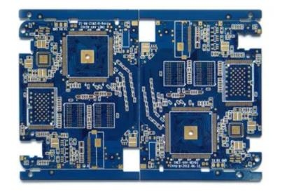
1 (20).jpg
5、 The SMAller the pin bending of high-speed electronic equipment, the better.
The lead wire of high-frequency PCB wiring is preferably full line, needs to roll, and can be folded in 45 degree line or arc. This requirement is only used to improve the fixed strength of copper foil in low-frequency circuit, and in high-frequency PCB, the content is satisfactory. One requirement is to reduce the external transmission and mutual coupling of high-frequency signals.
6、 Avoid circulation of traces.
Do not form a cycle of all types of high frequency signal wiring all or a lot. If unavoidable, keep the loop area as small as possible.
7、 The high frequency digital signal of the high frequency board is grounded and isolated from the analog signal ground.
When the analog ground wire, digital ground wire, etc. are connected to the public ground wire, high-frequency turbulent magnetic bead connection or direct isolation shall be used to select the local area suitable for single point interconnection. The ground potential of the high-frequency digital signal of the high-frequency board is generally inconsistent, and there is a certain voltage difference between them. Moreover, the ground wire of high-frequency digital signal generally has a very rich harmonic weight of high-frequency signal. When the digital signal ground is directly connected with the analog signal ground, the harmonics of the high-frequency signal will disturb the analog signal through the ground wire coupling. Therefore, in general, it is necessary to isolate the grounding of high-frequency digital signals and the grounding of analog signals, and the single point interconnection method or the interconnection of high-frequency turbulent magnetic beads in an appropriate orientation can be passed.
8、 It is necessary to ensure excellent signal impedance matching.
During signal transmission, when the impedance does not match, the signal will be reflected in the transmission channel, and the reflection will exceed the composite signal, causing the signal to fluctuate near the logic threshold.
The fundamental way to eliminate reflection is to make the impedance of the transmitted signal match well. Because the difference between the load impedance and the characteristic impedance of the transmission line is large, the reflection is also large. Therefore, the characteristic impedance of the signal transmission line should be equal to the load impedance as much as possible. At the same time, pay attention to that the transmission line on the PCB should not be abrupt or turn, and try to keep the impedance of each point of the transmission line continuous, otherwise there will be reflection between transmission lines. This requires the following routing rules to be followed when performing high-speed PCB routing:
USB cabling rules. USB signal differential routing is required. The line width is 10 mils, the line spacing is 6 mils, and the ground wire and signal wire are 6 mils apart.
HDMI wiring rules. HDMI signal differential wiring is required, with line width of 10 mils and line spacing of 6 mils. The interval between each HDMI differential signal pair exceeds 20 mils.
LVDS wiring rules. LVDS signal differential routing is required, with line width of 7mil and line spacing of 6mil, so as to control the differential signal impedance of HDMI at 100+- 15% ohm
DDR wiring rules. DDR1 wiring requires that the signal should not pass through the hole as much as possible. The width of signal lines is equal and the lines are equidistant. It is necessary for the line to comply with the 2W criterion to reduce crosstalk between signals. High frequency data is required for high-speed equipment of DDR2 and above. These lines are of equal length to ensure that the impedance of the signal matches.
9、 Adhere to the integrity of signal transmission.
Adhere to the integrity of signal transmission to avoid "ground bounce" caused by ground cutting.
10、 Watch out for "crosstalk" signal lines introduced by parallel lines.
PCB wiring of high frequency board shall pay attention to the "crosstalk" introduced by parallel lines of signal lines. Crosstalk refers to the coupling between signal lines that are not directly connected. Because high-frequency signals are transmitted along transmission lines in the form of electromagnetic waves, the signal lines act as antennas, and the energy of electromagnetic fields is transmitted around the transmission lines, and the electromagnetic field coupling between unwanted noise signal signals generated by each other is called crosstalk. The parameters of PCB circuit layer, the spacing of signal lines, the electrical characteristics of drivers and receivers, and the terminals of signal lines all have a certain impact on crosstalk. Therefore, in order to reduce the crosstalk of high-frequency signals, the following points should be done as far as possible in the wiring process:
The lines penetrating into the grounding or the grounding plane with serious crosstalk between two grounding wires can be isolated and reduce crosstalk under the conditions that the wiring space allows.
When there is time-varying electromagnetic field in the space around the signal line, if parallel dispersion cannot be avoided, a large area of "grounding" can be placed on the reverse side of the parallel signal line to greatly reduce disturbance.
On the prEMIse of wiring, the space is allowed. Add the spacing between adjacent signal lines and reduce the parallel length of signal lines. The clock line should be straight rather than parallel to the critical signal line.
If parallel traces in the same layer are almost inevitable, then in two adjacent layers, the trace directions need to be straight to each other.
In the digital circuit, the general clock signal is the signal with fast marginal change, and the external crosstalk is very large. Therefore, in the planning, the clock line should be surrounded by the ground wire and more grounding holes to reduce dispersion capacitance and then reduce crosstalk.
For high-frequency signal clock, try to use low-voltage differential clock signal and cover the ground. You need to pay attention to the integrity of the packaging.
Do not ground the unused input terminal, but ground it or connect it to the power supply (the power supply is also grounded in the high-frequency signal circuit). Because the suspension wire can be equivalent to the transmitting antenna, grounding can suppress the transmission. Practice has proved that this method can sometimes be used to eliminate crosstalk immediately. PCB manufacturers, PCB designers and PCBA processors will explain the layout suggestions of high-frequency boards from PCB manufacturers.


Telegram
Gerberファイル、BOMファイル、および設計ファイルをアップロードするだけで、KINGFORDチームは24時間以内に完全な見積もりを提供します。