
Kingfordは「高品質、短納期、小量の試作生産から量産まで」というお客様のニーズにお応えします

Crosstalk Analysis and Control in High Speed PCB design
This paper will introduce the methods of suppressing and improving signals, and design strategy PCB layout technology With the complexity of system design and the large-scale improvement of integration, electronIC system designers are engaged in circuit design above 100MHz, and the working frequency of bus has reached or exceeded 50MHz, some even exceeded 100MHz At present, about 50% of the design clock frequency exceeds 50MHz, and nearly 20% of the design main frequency exceeds 120MHz When the system operates at 50MHz, transmission line effect and signal integrity problems will occur; When the system clock reaches 120MHz, unless the knowLEDge of high-speed circuit design is used, the S based on traditional PCB design will not work Therefore, high speed circuit design technology has become a design method that electronic system designers must adopt The controllability of the design process can only be achieved by using the design technology of high-speed circuit designers
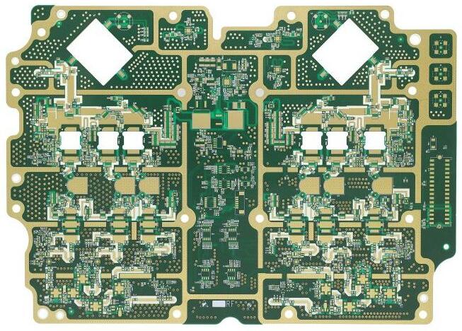
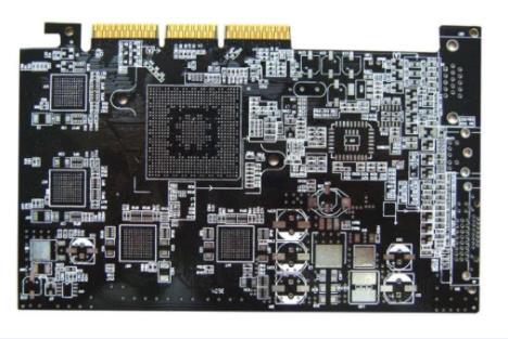
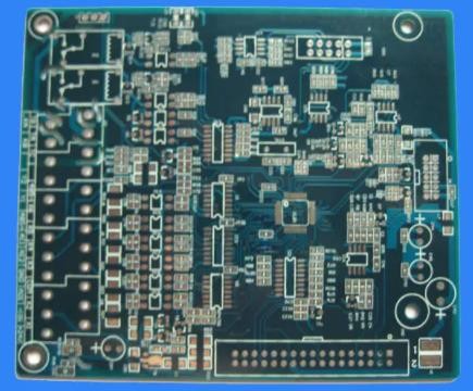
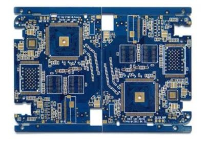
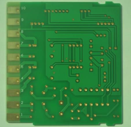
PCB board

At present, the increasingly complex transistor technology makes the transistor size SMAller and smaller. In summary, the signal transition edge of the equipment is faster and faster, which leads to the increasingly serious problems of signal integrity and electromagnetic compatibility in the field of high-speed digital circuit system design Signal integrity problems mainly include transmission line effects, such as reflection, time delay, ringing tone, signal overshoot and undershoot, and crosstalk between signals The signal crosstalk is very complex, involving many factors, complex computation and difficult to control Therefore, today's electronic product design urgently needs new ideas, processes, methods and technologies different from the traditional design environment, design processes and design methods EDA technology uses computers as tools The designer uses the hardware description language VHDL to complete the design files on the EDA software platform, and then the computer automatically completes the logic compilation, SIMplification, subdivision, synthesis, optimization, layout, wiring and analogy, until the modification and compilation, the logic mapping and programming of the specific target chip The emergence of EDA technology has greatly improved the efficiency and operability of circuit design and reduced the labor intensity of designers Using EDA tools, electronIC designers can design electronic systems, calculations, agreements, etc. according to concepts. A large amount of work can be completed through computers. From circuit design to the whole process of electronic products, they can design IC layout or PCB layout efficiency analysis Automatic processing on the computer The concept or category of EDA is now widely used EDA has many applications in machinery, electronics, communications, aerOSPace, chEMIcal industry, minerals, biology, medicine, military and other fields At present, EDA technology has been widely used in major companies, enterprises and institutions, as well as research and teaching departments For example, EDA technology may be involved in aircraft manufacturing from design, flight simulation performance test and characteristic analysis
Crosstalk Solutions
Crosstalk: It is the coupling between two signal lines Capacitive coupling causes coupling current and inductive coupling generates coupling voltage The parameters of the PCB layer, the distance between signal lines, the power characteristics of the driver and receiver, and the wire termination methods all have a certain impact on the crosstalk With the development of science and technology, the price of computers is getting lower and lower, the efficiency is getting better and better, the transmission rate of LAN is getting faster and faster, and the transmission medium of LAN is also changing from coaxial cable to twisted pair and optical fiber The original CAT1, CAT3 and CAT5 have developed to the current CAT5E, CAT6, CAT6A and CAT7 Although the efficiency of twisted pair is constantly improved, there is a parameter like a ghost accompanying twisted pair and equipped with twisted pair This parameter becomes more and more important Bad noise voltage signals caused by mutual coupling of electromagnetic fields between signals are called signal crosstalk If the crosstalk exceeds a certain value, the circuit may fail and the system will not work properly Solving the problem of crosstalk can be considered from the following aspects:
1) Reduce the conversion rate of the signal edge if possible. Generally, when selecting equipment, while meeting the design specifications, try to select slower equipment to avoid mixing different types of signals, because fast changing signals have potential crosstalk risks to slowly changing signals
2) Adopt shielding measures: It is an effective way to solve the problem of crosstalk to provide grounding for high-speed signals. However, the cladding leads to new wiring volume, which makes the originally limited wiring area more crowded In addition, in order to achieve the desired ground wire mask, the distance between ground points on the ground wire is critical, usually less than twice the signal variation length At the same time, the ground wire will also increase the distributed capacitance of the signal, which will increase the impedance of the transmission line and slow down the signal edge
3) Reasonable setting of layers and wiring: rational setting of wiring layers and wiring spacing, reducing the length of parallel signal lines (within the key length range). These measures can effectively reduce crosstalk
4) Setting different wiring layers: Setting different wiring layers for signals of different rates and setting the plane layer reasonably is also a good way to solve crosstalk.
5) Impedance matching: If the near end or far end terminal interference of the transmission line matches the interference of the transmission line, the amplitude of crosstalk can also be greatly reduced The purpose of crosstalk analysis is to quickly find, locate and solve the crosstalk problem in PCB implementation Generally speaking, analog tools and environment, simulation analysis and PCB layout environment are independent of each other After wiring, crosstalk analysis is performed to obtain crosstalk analysis, new wiring rules are derived and reconnected, and then analyzed and corrected From the simulation analysis, it can be seen that the actual crosstalk results are not the same and there is a big gap Therefore, a good tool should not only analyze crosstalk, but also apply crosstalk rules to routing In addition, conventional routing tools are only driven by physical rules, and routes used to control crosstalk can only be constrained by physical rules, such as setting line width and line spacing, and length of parallel lines Using signal integrity analysis and design toolset ICX can support real power rule driven routing Simulation analysis and wiring are completed in an environment Power rules and physical rules can be set during analogy, and automatic calculation can be carried out during wiring Signal integrity factors such as overshoot and crosstalk are automatically corrected according to the calculation results The connection speed is fast, which truly meets the actual power efficiency requirements
Signal Integrity Design for Crosstalk Control
High Speed PCB design rules are generally divided into two categories: physical rules and electrical rules The so-called physical rules refer to some design rules specified by the design engineer according to the physical dimensions, such as line width of 4Ml, line spacing of 4Ml, and length of parallel tracks of 4Ml Power rules refer to the design rules related to power characteristics or power efficiency, for example, the wiring delay is controlled between 1ns and 2ns, the total amount of crosstalk on a particular network is less than 70mV, and so on Once the physical and electrical rules are clearly defined, high-speed routers can be further explored At present, the high speed routes based on physical rules (physical rule driven) on the MARKet include AutoActive RE router, CCT router, BlazeRouter router and router editor router In fact, these routers are automatic routers driven by physical rules That is, these routers can only automatically meet the physical size requirements specified by the design engineer, and cannot be directly driven by high-speed power rules High speed routers driven directly by power rules are very important to ensure signal integrity in high-speed design Design engineers always have power rules, and design codes are also power rules In other words, our design must comply with electrical rules, not physical rules The final physical design implementation must meet the design power requirements Physical rules are just the conversion of electrical rules by component manufacturers or design engineers themselves We always hope that this transformation is equivalent and one-to-one This is not the case Taking the use of LVDS chips to complete high speed (up to 777.76Mbps) and long distance (up to 100M) data transmission as an example, since the signal swing of LVDS technology is 350mV, the general design specification always requires that the total line crosstalk value on the signal line should be less than or equal to 20% of the signal swing, that is, the total amount of crosstalk is 350mV * 20%=70mV, which is the power rule, The percentage of 20% depends on the LVDS noise tolerance, which can be obtained from the reference manual For IS U synthesizer, as long as the design engineer specifies the crosstalk value on the LVDS signal line, the wiring can be automatically adjusted and optimized to ensure that the power efficiency requirements are met, and all the surrounding signal lines will be automatically considered in the wiring process The influence of LVDS signal For routers driven by physical rules, some assumptions should be analyzed and considered first Design engineers always think that the crosstalk between signals only depends on the length of parallel lines between parallel signals. In this case, it can be used in high-speed circuits In the front-end environment of the design, some assumptions are analyzed For example, you can assume that the length of parallel wiring is 2.5 million, and then analyze the crosstalk between them This value may not be 70mV, but you can further adjust the parallel connection according to the conclusion If the length of the parallel line is controlled within the range of 7mil, then the design engineer thinks that as long as the length of the parallel line of the different line can be met within the range (signal cross-section value is controlled within 70mV), The design engineer obtained the layout and wiring of high-Speed PCB in the actual physical process Traditional high-speed routers can be guaranteed by this physical size requirement There are two problems. First, regular transformations are not equivalent First, the crosstalk between signals is not determined by the trace length between parallel signals, but also depends on the signal flow direction, the position of parallel line segments, and various factors, such as the existence or absence of matching, which may be difficult to predict or even fully explain before the actual implementation Therefore, after such conversion, it is impossible to ensure that these physical rules are met while the original power rules are met This is also a very important reason why the high-speed routers mentioned above cannot work normally even if they meet the rules Secondly, when converting these rules, it is almost impossible to consider multiple impacts at the same time For example, when considering signal crosstalk, it is difficult to consider the influence of all surrounding signal lines at the same time These two situations determine that high-speed routers based on physical rules will have big problems in high-speed and high complexity design. PCB board system and high-speed PCB board router based on power rules are better This problem has been solved The design of high speed PCB board hierarchy and system hierarchy is a complex process Signal integrity issues including signal crosstalk bring about changes in design concepts, design ideas, design processes and design methods To ensure that problems are identified quickly, categorically, and guided in new designs to prevent problems in high-speed system design, it has become the mainstream PCB design of high-speed systems today


Telegram
Gerberファイル、BOMファイル、および設計ファイルをアップロードするだけで、KINGFORDチームは24時間以内に完全な見積もりを提供します。