
Kingfordは「高品質、短納期、小量の試作生産から量産まで」というお客様のニーズにお応えします

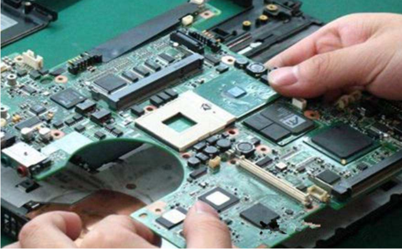
1.エンジニアリング回路基板の静電容量損傷の故障特性とメンテナンス
コンデンサの損傷による故障は、電子機器の中で最も多く、特に電解コンデンサの損傷が最も多くなっています。
静電容量は次のように損傷します。 1. 静電容量が小さくなります。 2.容量の完全な損失; 3.漏電; 4.短絡。

コンデンサは回路内でさまざまな役割を果たし、コンデンサによって引き起こされる障害には独自の特性があります。 産業用制御回路基板では、デジタル回路が圧倒的多数を占めています。 コンデンサは主に電力フィルタとして使用され、信号結合および発振回路として使用されるコンデンサはほとんどありません。 スイッチング電源に使用されている電解コンデンサが破損すると、スイッチング電源が振動せず、電圧が出力されない場合があります。 または、出力電圧のフィルタリングがうまくいかず、電圧が不安定なために回路ロジックが混乱しています。これは、マシンが動作しているときにマシンが良いか悪いか、または起動できないことを意味します。 コンデンサがデジタル回路の電源の正極と負極の間にある場合、障害性能は上記と同じです。
これは、コンピューターのマザーボードで特に顕著です。 多くのコンピュータは起動できないか、数年使用した後に起動できます。 シャーシを開けると、電解コンデンサが膨らむ現象がよく見られます。 容量を測定するためにコンデンサを取り外した場合、実際の値よりもはるかに低いことがわかります。
コンデンサの寿命は、周囲温度に直接関係します。 周囲温度が高いほど、コンデンサの寿命は短くなります。 このルールは電解コンデンサだけでなく、他のコンデンサにも当てはまります。 したがって、障害コンデンサを探すときは、ラジエータや高出力コンポーネントの近くなど、熱源に近いコンデンサに注目する必要があります。 近ければ近いほど、損傷を受ける可能性が高くなります。
2. 耐性損傷の特徴と判別
分解と溶接を兼ねた回路を修理する際に、初心者が抵抗を投げてオンにすることがよく見られます。 実際には、それははるかに修復されています。 耐性のダメージ特性を理解している限り、多くの時間を費やす必要はありません。
抵抗は電気機器で最も多くの部品ですが、損傷率が最も高い部品ではありません。 開回路は、最も一般的な抵抗損傷です。 抵抗値が大きくなることは少なく、抵抗値が小さくなることもまれです。 一般的なタイプには、炭素皮膜抵抗、金属皮膜抵抗、巻線抵抗、ヒューズ抵抗などがあります。
最初の 2 種類の抵抗器が最も広く使用されており、その損傷特性は、まず、低抵抗 (100 Ω 未満) と高抵抗 (100 k Ω 以上) の損傷率が高く、中抵抗の損傷率 ( 数百オームから数十キロオームなど)はまれです。 第二に、低抵抗の抵抗が損傷すると、しばしば焼けて黒くなり、見つけやすくなりますが、高抵抗の抵抗が損傷すると、痕跡がほとんどありません。
巻線抵抗は一般に大電流制限に使用され、抵抗値は大きくありません。 円筒状の巻線抵抗が焼損すると、一部が黒くなったり、表面が割れたり、痕跡がなくなったりします。 セメント抵抗は一種の巻線抵抗であり、燃え尽きると壊れる可能性があり、そうでなければ目に見える痕跡はありません。 ヒューズ抵抗器が燃え尽きると、一部の表面は皮膚の一部が吹き飛ばされ、一部には痕跡がありませんが、決して燃えたり黒くなったりすることはありません. 上記の特性により、抵抗のチェックに集中し、損傷した抵抗をすばやく見つけることができます。
上記の特性によると、回路基板の低抵抗抵抗に黒焦げの兆候があるかどうかを最初に観察できます。 次に、抵抗が損傷し、高抵抗抵抗が損傷しやすいときのほとんどの開回路または大きな抵抗値の特性に応じて、マルチメータを使用して、高抵抗抵抗の両端の抵抗を直接測定できます。 回路基板。 測定された抵抗値が公称抵抗値よりも大きい場合, 抵抗が損傷している必要があります. 回路内)。 測定された抵抗値が公称抵抗値より小さい場合、通常は無視されます。 このようにして、回路基板上の各抵抗が 1 回測定されます。 誤って1000体を「殺して」しまっても、1体も逃すことはありません。
3. オペアンプの判定方法
オペアンプの良し悪しを判断するのは、かなりの数の電子メンテナーにとって難しいことです。 こちらでお話しさせていただきますので、参考になれば幸いです。
理想的なオペアンプは「仮想ショート」と「仮想ブレーク」という特性を持っており、リニアアプリケーションのオペアンプ回路の解析に非常に役立ちます。 線形アプリケーションを保証するために、オペアンプは閉ループ (負帰還) で動作する必要があります。 負帰還がない場合、開ループ増幅中のオペアンプはコンパレータになります。 デバイスの良し悪しを判断したい場合は、まずそのデバイスが回路内でアンプとして使用されているかコンパレータとして使用されているかを区別する必要があります。
4. マルチメーターでSMTコンポーネントをテストする裏技
一部のSMDコンポーネントは非常に小さいため、通常のマルチメータープローブでテストおよび修理するのは不便です. まず、ショートしやすい。 第二に、絶縁コーティングでコーティングされた回路基板がコンポーネントピンの金属部分に接触するのは不便です。 これは、検出に非常に便利な簡単な方法です。
最小サイズの 2 本の縫い針 (深い工業用制御保守技術のコラム) をマルチメータ プローブに近づけ、次に細い銅線をマルチ ストランド ケーブルに取り、細い銅線を使用してプローブと縫い針を結びます。 しっかりとはんだ付けします。 このように、先端の小さなスタイラスでSMTコンポーネントを測定する場合、短絡の危険はありません。 また、チップは絶縁コーティングに穴を開けたり、キーパーツを直接叩いたり、フィルムを傷つけたりする必要がなくなります。
5. PCB の公共電源の短絡のトラブルシューティング方法
回路基板のメンテナンス中に、公共の電源に短絡が発生すると、大きな問題になることがよくあります。 多くのデバイスが同じ電源を共有しているため、この電源を使用する各デバイスは短絡の疑いがあります。 ボード上に多くのコンポーネントがない場合は、「くわアース」法を使用して短絡点を見つけることができます。 コンポーネントが多すぎる場合、「鍬の土」が状況に対応できるかどうかは運次第です。 ここでは、より効果的な方法をお勧めします。 この方法では、半分の労力で 2 倍の結果を得ることができ、多くの場合、障害点をすばやく見つけることができます。
There should be a power supply with adjustable voltage and current. The voltage is 0-30V, and the current is 0-3A. This power supply is inexpensive, about 300 yuan. Adjust the open circuit voltage to the power supply voltage level of the devICe. First, adjust the current to the minimum. Apply this voltage to the power supply voltage point of the circuit, such as the 5V and 0V terminals of 74 series chips. Slowly increase the current depending on the degree of short circuit. Touch the device with your hand. When you feel that a device is obviously hot, this is often a damaged component. You can take it down for further measurement and confirmation. Of course, during operation, the voltage must not exceed the working voltage of the device, and the connection must not be reversed, otherwise other good devices will be burned.
6. A SMAll rubber to solve big problems
More and more boards are used in industrial control, and many of them are inserted into the slots with gold fingers Due to the harsh environment of the industrial site and the dusty, humid and corrosive gas environment, it is easy to cause the board to have a bad contact fault. Many friends may solve the problem by replacing the board, but the cost of purchasing the board is very considerable, especially for some imported equipment. In fact, you might as well use an eraser to repeatedly wipe the golden finger, clean up the dirt on the golden finger, and try the machine again. Maybe it will solve the problem! The method is SIMple and practical.
7. Analysis of electrical faults of good and bad
In terms of probability, the electrical faults of good and bad times generally include the following situations:
1) . Poor contact
Poor contact between the board and slot, no connection when the cable is broken, poor contact between the cable plug and terminal block, and faulty soldering of components are all included in this category;
2) . Signal is disturbed
For digital circuits, under specific conditions, faults will appear. It is possible that the control system is indeed affected by too much interference, and the parameters of individual components or the overall performance parameters of the circuit board have changed, making the anti-interference ability tend to the critical point, thus causing faults;
3) Poor thermal stability of components
From a large number of maintenance practices, the thermal stability of electrolytic capacitor is poor, followed by other capacitors, triodes, diodes, ICs, resistors, etc;
4) There is moisture and dust on PCB.
Moisture and dust will conduct electricity with resistance effect, and the resistance value will change in the process of thermal expansion and cold contraction. This resistance value has a parallel effect with other components. If this effect is strong, the circuit parameters will be changed, causing faults;
5) Software is also a consideration
Many parameters in the circuit are adjusted by software. The margin of some parameters is adjusted too low, which is in the critical range. When the operating condition of the machine meets the reason for the software to judge the failure, the alarm will appear.
8. How to quickly find component data
Modern electronic products are various, and there are more and more components. In the field of circuit board welding and maintenance, especially in the field of industrial circuit board maintenance, many components have never been seen or even heard of. In addition, even if the data of components in a certain type of board is complete, it is necessary to read and analyze these data one by one in the computer. If there is no quick search method, the maintenance efficiency will be greatly reduced, In the field of industrial electronic maintenance, efficiency is money.
SMTチップ加工およびPCBA製造におけるフラックスの特徴
10-23,2022


Telegram
Gerberファイル、BOMファイル、および設計ファイルをアップロードするだけで、KINGFORDチームは24時間以内に完全な見積もりを提供します。